With the rapid development of the automobile industry, higher requirements are put forward on the materials, design and manufacturing of parts, and high integration, high performance, and low cost have become the development trend. Both the oil pan and the lower cylinder block are important parts of the automobile engine. By integrating the lower cylinder block balance shaft and the oil pan collection and filtering function on the same part, the weight and volume of the engine are effectively reduced. However, due to the complex structure and large wall thickness changes, it needs to be split into different products and processed separately and then combined and processed, resulting in difficulties in product manufacturing.
The integrated oil pan of an engine studied in this subject contains three castings: the oil pan body, the balance bearing cover and a single balance bearing cover. Using A380 modified alloy material, the average wall thickness of the casting is 3 mm, the minimum wall thickness is 2.5 mm, and the mass of the blank is 10.74 kg. The inner cavity is required to be leak-free under 300 kPa, and the oil passage is not leaked at 600 kPa and the temperature exceeds 60 ℃. Leakage, used in 1.5T engines, with an annual output of 400,000 pieces, which is a typical complex oil pan casting.
Technical points of die casting design
1.1 Runner design
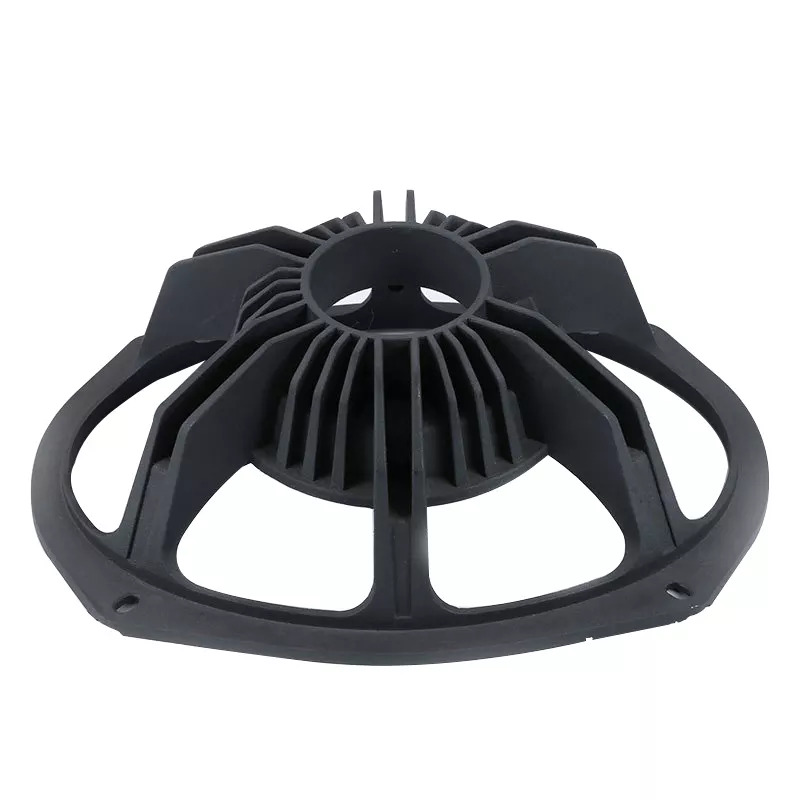
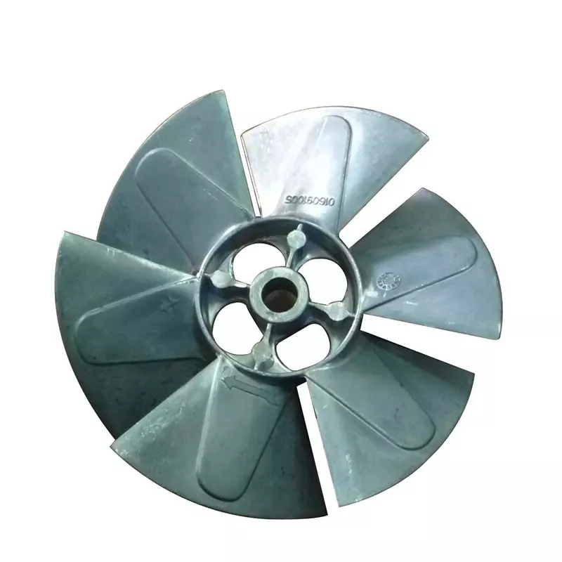
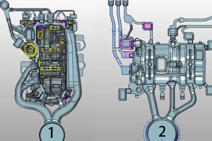
Casting 1 adopts a three-sided pouring design, but focuses on the overall pouring on one side, as shown in Figure 1. As the product is long (up and down length reaches 437.2 mm), the three-sided pouring design can effectively alleviate the problem of long process, so as to fill the product in different areas. However, considering that the overall wall thickness of the product is thicker and there are many raised inserts at the pouring position, in order to avoid the fluidity of the molten aluminum being blocked, the filling on one side is strengthened, and the cross-sectional area is gradually narrowed as a whole to accelerate the flow of the molten aluminum. Design sprue.
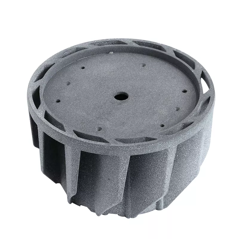
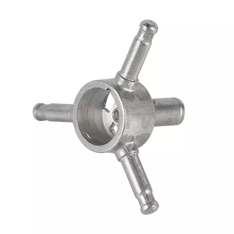
Casting 2 is a balance bearing cover, with a relatively simple shape, only the middle two balance shaft oil grooves are thick. Based on the simple flow pattern of the molten aluminum, in order to save costs and increase the effective output rate of the molten aluminum, a single-side pouring scheme is adopted, and the gate is placed in the wall thickness area for feeding, as shown in Figure 2.
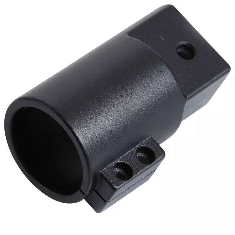
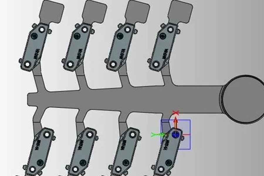
Casting 3 is a single balance shaft tile cover with smaller part (size 63 mm) × 15 mm × The design of one cavity and eight molds is adopted for filling and pouring, as shown in Fig. 3.
1.2 Exhaust method
For complex casting 1, high vacuum is used for exhaust. Casting 2, using ordinary "washboard" type exhaust block. Casting 3 directly adopts the slag bag and the mold core exhaust channel at the tail of the slag bag. The main points of the exhaust technology of casting 1 are emphasized here.
Since the high-pressure oil passages and oil filters of the castings are concentrated in the water tail, the exhaust effect of the water tail is the key factor that determines the internal quality of these locations. Casting 1 uses high vacuum exhaust to reduce the air pressure in the negative pressure zone of the water tail of the casting. First of all, the volume of the vacuum tank must be selected ≥ 800 L (800 L here is more than 10 times the volume of the mold containing the cavity and the trough) to quickly form the negative pressure channel. Secondly, the pipeline connecting the mold and the vacuum machine must be sealed and airtight, and the vacuum degree of the pipeline should be kept within 2 000 Pa. Third, the mold is sealed with a sealing tape, and all the thimble and core pins are coated with sealant. After the mold is closed, the cavity vacuum must be kept within 4 000 Pa. Finally, choose the best production of the sealed punch, or use the extended version of the punch to increase the sealing area of the punch, and effectively alleviate the leakage of air into the cavity.
1.3 Mold temperature
Due to the characteristics of high vacuum, the molten aluminum is not completely filled in accordance with the theoretical fluid state (see Figure 4), and the molten aluminum is easy to quickly solidify in certain places when sucked into it, causing die casting defects such as die casting pores, shrinkage holes, and cracks. The product of this casting 1 starts to vacuum when the punch moves to the position of 410 mm (aluminum liquid fullness reaches the requirement of 70%), and closes the vacuum at the position of 540 mm. Time), the vacuum stroke is 130 mm, and the time is 0.874 s. In such a short period of time, it must be ensured that the drawn aluminum liquid will not solidify in an important position in the tail of the water in advance. Therefore, the mold temperature at these positions is controlled at 220 ℃ and 180 ℃ respectively by using an oil temperature machine. Increased mold temperature and enhanced liquidity of molten aluminum are the key to ensuring the internal quality of these two important locations.
Castings 2 and 3 are relatively simple in structure, short in filling distance, and easy to form. They do not require high mold temperature, as long as the mold surface temperature is high and the product does not turn black.
1.4 Mold cooling options
This casting 1 uses super-point cooling technology and intermittent water supply technology. Since the casting production needs to maintain a higher temperature, and there are more insert bosses on the movable mold side, it is necessary to ensure that the high temperature is not only ensured, but also that the raised inserts will not form hot joints and cause shrinkage cracking and other defects. The cutting process is performed for each insert, and the spot cooling is driven into the interior of the insert. The synchronous peripheral equipment uses an intermittent water supply method. During the product solidification stage, the solenoid valve is opened to cool the product locally. This not only obtains a higher temperature, but also obtains a good cooling effect. The super-point cooling process is designed for die-casting core needles, as shown by the arrow in Figure 1. A 4 mm needle in the middle of the wall thickness area will directly cause shrinkage. The super-point cooling design is used for the 4 mm needle, which can solve the pore problem of the threaded hole. Similarly, in other cross-hot spots, the super-point cold needle design is used where the needle can be ejected, which greatly alleviates the problems of burns, stomata, and broken needles. The time setting of super-point cooling and intermittent water supply needs to consider the wall thickness of the material punched hole and its location. Therefore, the cold needles in these different areas need to be zoned control.
Casting 2 only has a 4 mm oil groove hole in the middle of the balance shaft and a Φ8 mm bolt hole at the feed inlet, which uses super-point cold control. Because after the aluminum liquid is scoured, a loose channel will be formed between the middle wall thickness areas, an over-point cold needle must be used to forcibly increase the dense layer around the pinhole, with a delay of 1 s and cooling for 10 s. The 16 small needles of Φ8 mm in casting 3 all use super-point cold control to maintain the thickness of the dense layer near the pinhole.
1.5 Selection of local extrusion technology
The local extrusion pin can quickly solve the shrinkage in the wall thickness area and is widely used in the field of die casting. The analysis of mold flow hot joints is shown in Figure 5. There are many hot joints in casting 1, and the position of the extrusion pins needs to be reasonably arranged. First, eliminate the hot nodes that can be eliminated by using the cold needle, and secondly eliminate the hot nodes that are not in key positions. Finally, you need to consider the arrangement of the squeeze pin cylinder in the internal space of the mold. It is generally arranged at a point where the structure is complicated and air leakage is prevented ..
Key points of die casting process control
2.1 Control of spray flow during die casting
During the die-casting process, the spray flow rate is measured separately by the moving and fixed molds, the moving mold is controlled at 3 200 mL, and the fixed mold is controlled at 2 200 mL. In addition, the upper and lower deviation values are set separately for the dynamic and fixed mold flow rates. Since the selected electromagnetic flowmeter has an accuracy of 50 mL, the setting deviation is ±200 mL, and 200 mL is the actual measured value after one spray gun is reduced. During the production process, if the deviation value is exceeded, an alarm signal will be output directly to stop the die-casting production cycle. Therefore, it can effectively prevent the spraying from being blocked due to the spray gun, which may cause mold sticking and burns.
2.2 Process control of molten aluminum temperature
Since the heat preservation effect of the holding furnace is good, but the heating rate is slower than that of the quantitative furnace, the incoming temperature of the molten aluminum needs to be controlled. The casting temperature of molten aluminum is 675±10°C, so the incoming temperature of molten aluminum in the transportation ladle must be kept above 700°C. Feeding below this temperature will affect the flow state of the molten aluminum during the filling process, resulting in an increase in the proportion of pores at local locations. Adding materials above 730 ℃ will cause serious burnt and sticking of aluminum on the surface of the mold, which will affect the appearance quality of the casting. Set the temperature alarm of the molten aluminum for the holding furnace. If the pouring temperature is not within the range, the holding furnace will alarm and stop the die-casting production cycle, which can effectively prevent the defects caused by the temperature deviation of the molten aluminum.
2.3 Vacuum control
Since the casting 1 mold is sealed with a movable and fixed mold sealing tape, all the thimble and core pins are sealed by applying sealant, and the chute is also an integral chute, but the punch does not use a special sealing punch, but uses an extension Plate punch (extended to 150 mm). In such a sealed condition, an alarm will be triggered when the vacuum degree is set to exceed 4 kPa (4 kPa is an empirical alarm value set according to the high pass rate during the production process), and the vacuum degree is generally around 2.3k Pa . The cleanliness and clogging values are generally close to 101 kPa, and the set alarm value is 90 kPa (90 kPa is set according to the cleaning cycle of the filter tank in the factory). At the end of a cleaning cycle, the vacuum valve filter tank should be cleaned in time. Failure to clean it will affect the vacuuming effect. The setting value of the vacuum tank is 1 kPa, which is generally between 2.2 and 400 Pa. As long as the required value is exceeded, an alarm will be issued and the die casting machine will be shut down.
2.4 Monitoring of the actual parameters of injection
The die-casting machine adopts the domestic Ube 1650T model. In addition to its own die-casting machine parameter control system, it also uses a two-dimensional code traceability system (called MES system in the factory) to connect the die-casting machine and peripheral auxiliary equipment so that the MES system can Read the production parameters of each mold in real time and feed them back to the cloud for comparison in the cloud (the cloud comparison value is entered into the cloud in advance as required, and different range values are output according to the actual achievement of different parameters. For example, the slow speed is ± 0.05 m/s, the high speed is ±3 m/s, etc., see Table 2), products that exceed the range after comparison will be locked by the system and judged as unqualified. Cloud Big Data also regularly calculates the real-time relationship between product obsolescence and parameter changes based on the updated data volume. Find out the reasons for the fluctuations in the scrap rate within a period of time, and improve the qualified rate of maintaining products. There are fluctuations in the die-casting production process, which can quickly find out the problem points and effectively promote a virtuous cycle on the spot.
2.5 Control of die-casting water transportation
At the beginning of the water transportation, each line uses a solenoid valve to control the time of direct cooling or ordinary point cold water transportation. The water pressure is 0.4 MPa and the water temperature is 30 ℃ pure water. Except for trough, material sleeve, punch, split cone and material sleeve forced cold plate which are normally open and direct cooling, all other direct cooling (water barriers) and large point cooling are controlled by solenoid valve, delay 3 s, cooling 15 s to ensure the mold temperature. All the needles, from Φ4 mm to Φ14 mm (the central tube from Φ1.5 mm to Φ5.5 mm) are controlled by super-point cold, the super-point cold water transport pressure is 10 MPa, and the water transport temperature is 10 ℃ (here The temperature cannot be set too low, too low will take away more heat, but it will easily cause broken needles), each group of super cold needles of the same size does not exceed 8 (more than 8 needles exceed the diameter of the diameter G1/2 connecting pipe diameter ), all the needles are combined into a total of 6 groups, except for the Φ4 mm point cold needle, the delay time is 5 s and the cooling is 13 s, and the Φ4 mm point cold needle is set to delay 4 s and the cooling time is 13 s to target the mold temperature field. In the area that needs to be cooled quickly, reduce the occurrence of hot spots. It not only guarantees the balance and heat preservation of mold temperature, but also eliminates local hot spots and guarantees product quality.
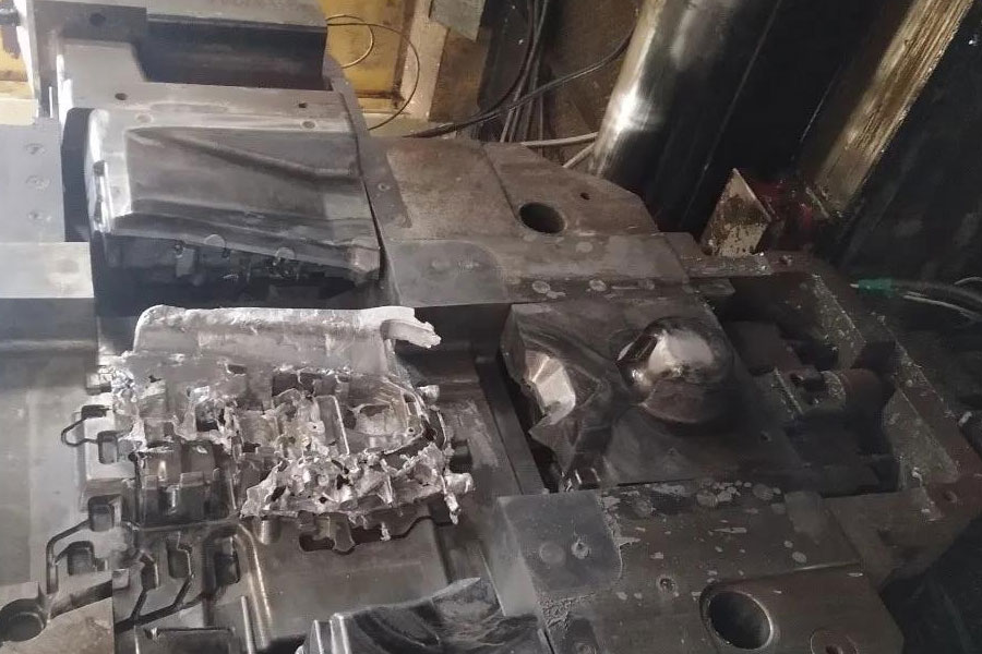
3. The quality of the new multifunctional oil pan. The three products are produced on two different machines, and the daily output is as high as 980 pieces/day, 1,500 pieces/day, and 12,000 pieces/day from casting 1 to casting 3. The overall pass rate of the three products until the final assembly is as high as 97%. Figure 8 is a picture of the appearance of the castings 1, 2 and the internal quality of the castings 1, 2, and 3.