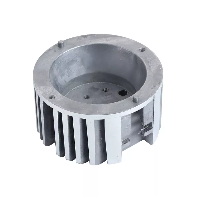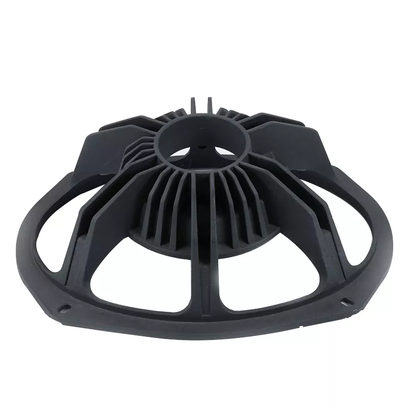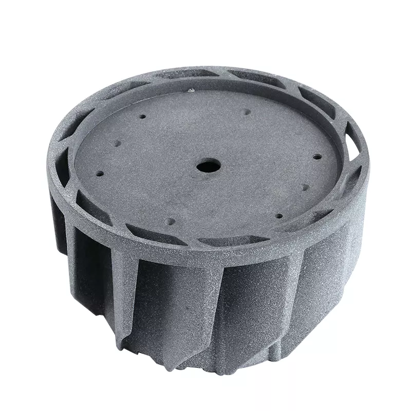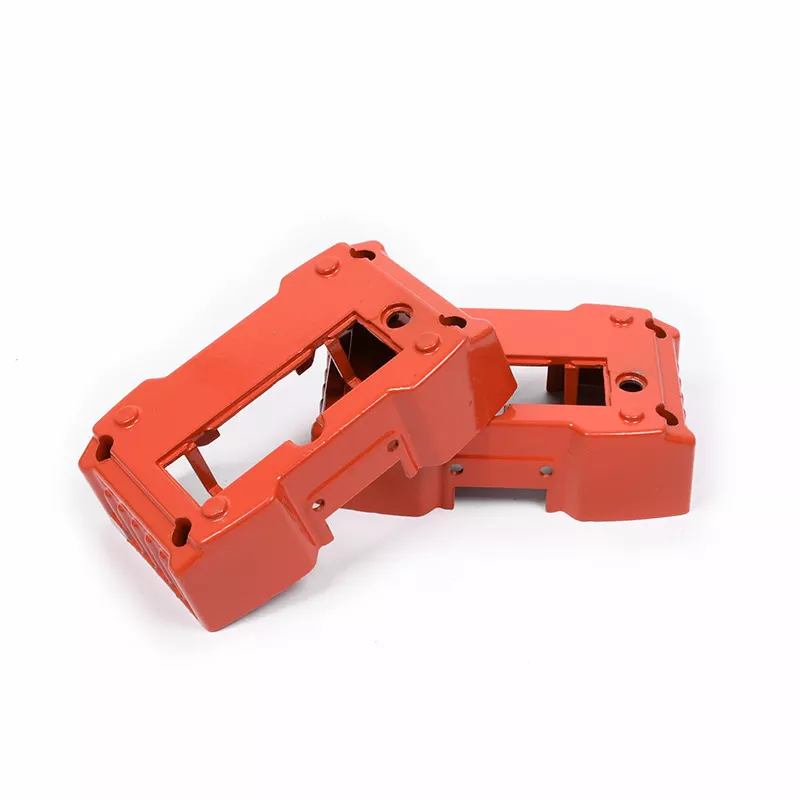
This article first analyzes the structure and die-casting process of the aluminum alloy shell, and uses UG software to complete the design of the aluminum alloy shell die-casting mold. Proved by practice, the designed die-casting is reasonable, the surface of the obtained casting is smooth and clean, and the product quality meets the requirements.
Analysis of the structure and process of die-casting parts of aluminum alloy rear shell
Die casting process parameter design
2.1 Die-casting machine selection When choosing a die-casting machine, the clamping force must be determined first. The clamping force has two functions: one is used to balance the back pressure to achieve the purpose of locking the parting surface; the other is to prevent splashing molten metal to achieve the purpose of achieving the target dimensional accuracy. There is no partial expansion force in the designed casting, because this mold has no side core pulling (the die casting has no side holes and undercuts). Therefore, F lock ≥ KF main=1.25×1288.352=1610.44kN. According to the above calculation, the value of the clamping force and the weight of the casting are obtained. According to these two main factors, the die-casting machine is selected, and the final selected model is: horizontal cold-chamber die-casting machine (2500kN)———J1125 type, main parameters:
2.2 Die-casting pressure Die-casting pressure is one of the main parameters in the die-casting process. Therefore, it is of great significance to grasp the pressure change of liquid metal during the die-casting process, and to reasonably control the pressure at each stage of the die-casting process:
2.3 Die-casting speed The choice of die-casting speed has the following two aspects: injection speed selection and filling speed selection. The choice of the two speeds is very important, which directly determines the internal and external quality and contour definition of the casting. Factors to be considered when selecting the filling speed:
Specific choices:
2.4 Die-casting time determines the die-casting time, which consists of three parts of the required time: filling time, holding time and the time that the die-casting part stays in the die-casting mold. Several factors combined to produce this result: pressure, speed, temperature, molten metal characteristics, as well as casting structure (mainly wall thickness and volume) and mold structure (especially the gating system and drain system) and other factors. The filling time is mostly between 0.01 and 0.2s. The length is determined by the size of the casting and the complexity of the structure: a casting with a simple structure and a large volume requires a relatively long filling time; a casting with a more complex structure and a smaller wall thickness requires a short time. After practical tests, the filling time is set at about 0.2s, which is reasonable for the medium and small aluminum alloy die castings designed in this paper. The function of holding pressure time is: the injection punch has enough time to apply pressure to the unsolidified metal, so that the crystallization process can be carried out under pressure, which enhances the feeding and successfully obtains a dense structure. Factors affecting the length of time: the melting point of the selected alloy, the crystallization temperature range and the wall thickness of the casting. Castings with high melting point, large range and large wall thickness require a long time, 2~3s; when the determined time is too short, shrinkage will appear, but it does not have a significant effect if the holding time is prolonged. 1~2s is the general holding time range. The average wall thickness of the casting in this design is 3mm. Considering its structure and alloy properties, 3s is selected as the holding time. 2.5 Die-casting temperature The main process parameters to ensure qualified castings—the pouring temperature of molten metal and the working temperature of the mold. There are many factors that affect it: the structure of the casting, wall thickness, filling pressure, speed, and alloy types. It is necessary to comprehensively consider the above parameters to ensure that the die-casting temperature is stable within a reasonable range and provide good filling conditions. If the pouring temperature is not within a reasonable range, the quality of the product will be degraded or even unqualified:
①Excessive pouring temperature — will cause excessive shrinkage during cooling, the product is prone to cracks, larger grains, and poor mechanics Performance, and even cause mold sticking, reduce mold life;
② Too low pouring temperature-cause defects including cold barrier, surface pattern and insufficient pouring. In order to obtain qualified castings, in addition to pouring temperature, pressure, die-casting mold temperature, filling speed and the alloy selected for castings should also be considered at the same time. The die-casting parts are made of aluminum-silicon alloy. According to its fluidity and mold characteristics, 620℃ is selected as the die-casting temperature.
Structure design of die casting die casting of back shell
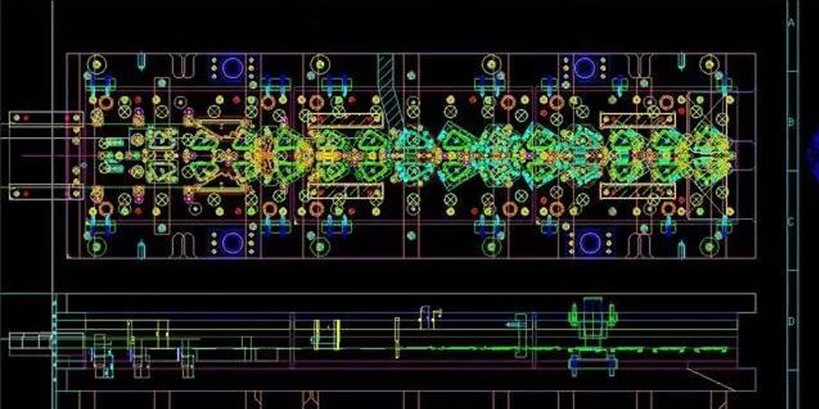
3.1 Determination of Parting Surface The part has a simple structure. According to the principle of parting surface selection, the largest projection section should be selected, as shown in Figure 2.
3.2 Design of the gating system The gating system is composed of four parts:
Specific design:
3.3 Design of overflow tank and exhaust system The structural design of the overflow tank is carried out, and the cross-sectional shape selected by comprehensive consideration of various factors is trapezoidal (Figure 4). A reasonable structure has the following functions:
3.4 Design of the ejection system In the die-casting process, after a complete forming cycle is completed, the die needs to be opened to take the die-cast part, and the wrapped die-cast part will be found on the side of the punch, which needs to be removed. This task requires an additional one Kind of top piece mechanism to perform. The ejector system occupies an important position in the mold structure design. There are three main parts of the ejector system:
Design limit devices in the system:
3.5 Calculation of the size of the formed part
3.5.1 Cavity and core size:
3.5.2 Calculate the center distance and position size: where: L-the center distance of the forming part and the average size of the position (mm); L-the average size of the die casting center distance and the position (mm).
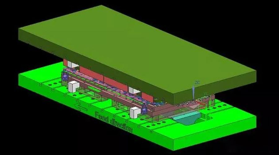
3.6 The design of the cooling system chooses an efficient and easy-to-control mold cooling method—water cooling to obtain high-quality castings and long mold life. The cooling effect of water cooling depends on the layout of the cooling channel, which is arranged in the cavity:
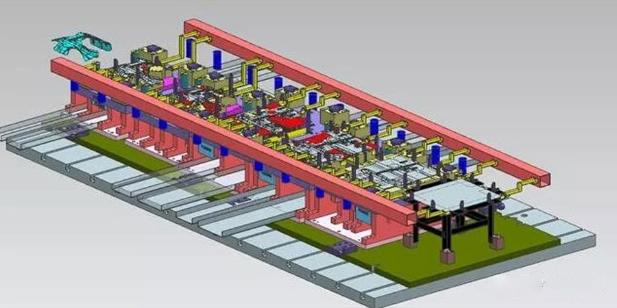
3.7 General Assembly Drawing of Die-casting Mould Make the general assembly drawing of the die-casting mould of the back shell cover (Figure 6). The die-casting mold is composed of two parts: a fixed mold and a movable mold. The fixed mold is stationary and is located on the fixed mold plate. The movable mold moves with the follower plate and is located on the follower mold fixed plate. The mold is closed and opened by the movement of the movable mold relative to the movable mold.
① Mold clamping: the two are closed to form a cavity, and the cavity is filled with molten metal under high pressure using a gating system; ② mold opening: the two are separated after the pressure is maintained, and the ejection mechanism completes the task of ejecting products from the cavity.
This article uses UG software to model the back cover parts, and completes the process analysis, die casting process parameters and mold structure design of the back cover parts. The cavity is limited by the following factors: manufacturing, process and production Efficiency, etc., considering the above factors comprehensively, it is determined as a more reasonable one-mold four-cavity layout. Practical production shows that the die-casting specific pressure of 90MPa is selected, the die-casting speed is selected in the range of 20-90m/s, the casting time of 0.2s, the holding time of 3s, and the die-casting temperature of 620℃, the resulting rear shell stuffy cover It has a smooth surface and meets product quality requirements.