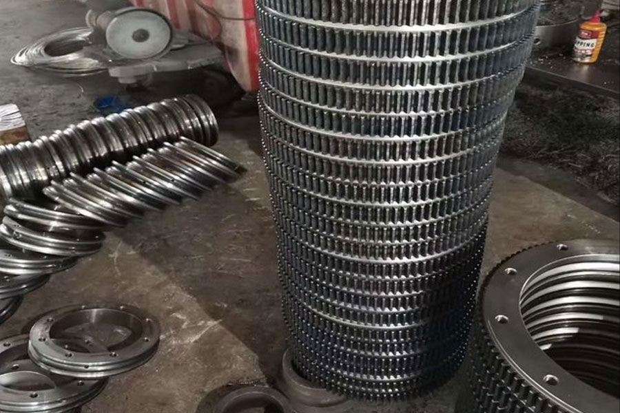
As a key component of construction machinery, slewing bearings are currently used in the market with nearly 10 million units. The main failure modes of the slewing ring are raceway wear, tooth surface wear, raceway cracks and tooth fractures, etc. The tooth surface cracks or fractures directly cause the slewing ring to be scrapped, and the raceway cracks will accelerate the damage of the slewing ring and greatly reduce the slewing ring design life. This paper selects the early cracks during the use of the soft belt of the slewing ring raceway to analyze and propose preventive measures.
1. Crack product description
The cracked product in this article is used for the slewing bearing of a 6t excavator, with a slewing center diameter of 730 and a rolling diameter of 22mm. In order to test the service life of the slewing ring, a loading test was carried out by simulating the actual working conditions as shown in Figure 1. After loading 30,000 revolutions, cracks in the soft zone were found.
The product process adopts scanning induction quenching, after quenching, it is tempered at a low temperature of 180~200℃, and then undergoes MT flaw detection. Due to the scanning induction hardening process of this product, a process soft zone must be reserved at the blockage, as shown between the two lines in Figure 2. After flaw detection, no cracks were found in this product, and subsequent processing was carried out.
2. Crack analysis
As mentioned earlier, after quenching and tempering, a comprehensive MT inspection was carried out on the workpiece. No cracks were found in the workpiece. The crack was found to be visible to the naked eye after the workpiece was loaded. It can be confirmed that the crack is caused by the bearing force.
Analysis of the cause of crack 1: In Figure 4, the crack is located in the transition zone between the matrix and the quenching. The matrix structure area has severe plastic deformation (see Figure 9), and a small amount of martensite appears in the transition zone (see Figure 4) and gradually becomes quenched. The hard zone transitions to the martensite zone (see Figure 7), and the yield strength gradually increases. Between the matrix and the transition zone, stress concentration is likely to occur during the repeated rolling process. After reaching the ultimate yield strength in this zone, cracks will occur and spread along the transition layer.
Analysis of the cause of crack 2: When the workpiece is subjected to induction quenching, the tempering zone is reserved for the process in Figure 5, and the structure is the matrix structure without quenching. It can be seen from the figure that there is a plastic deformation consistent with the direction of loading and running, and serious streamline deformation of the tissue occurs. After the workpiece is loaded, the unquenched yield strength is low. When the stress exceeds the yield limit of the material, plastic deformation is caused. After repeated rolling, the crystal grains slip and separate along the slip surface under the action of the stress. Move the surface to separate the cracks.
3. Preventive measures
Through the above analysis, it can be concluded that the cracks produced by the product are due to the load failure cracks of the workpiece after the soft zone of the workpiece is loaded. According to the industry's experimental research class, the following measures are adopted to prevent cracks in the soft zone:


